Conway's Game of Life on the NES in Rust
This post is about a Rust program…
$ cargo install conway-nes
…that prints out a NES binary…
$ conway-nes > life.nes
…that runs Conway’s Game of Life!
$ fceux life.nes # fceux is a NES emulator

When running in an emulator, press any button on your controller to restart from a randomized state.
NES Rendering
The NES displays 2 types of graphics:
![]()
Sprites are 8x8 pixel tiles which can be positioned at specific pixel coordinates, usually used for game characters and objects:
![]()
The background is a 2D grid of 8x8 pixel tiles, called a nametable. Individual tiles can be replaced, and the entire background can be scrolled smoothly. It’s typically used for mostly-static backgrounds and user-interface elements:
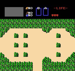
For Conway’s Game of Life, I only render the background, and replace nametable entries to keep the grid of tiles up to date with the state of the cells. NES graphics hardware is not optimized for frequent large changes to nametables. Fortunately, most frame-to-frame changes in Conway’s Game of Life are relatively small.

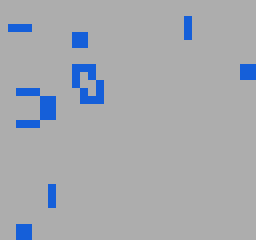
When starting from a random state where each cell has a 50% chance of being alive, the first few frames have dramatic frame-to-frame differences.


The NES processor is too slow relative to the framerate of its graphics hardware (in particular the vertical-blanking interval), to update the entire nametable each frame, so when the frame-to-frame difference is large, it requires several frames to perform the update.
The renderer takes a variable number of frames to render a single generation of Game of Life, taking fewer frames when inter-generation change is less dramatic. This is a slowed down recording in which the variability of the effective frame rate is clearly visible.

Quick intro to NES Background Graphics
The background nametable is stored in video memory. This is memory connected to the graphics chip, and isn’t directly accessible to the CPU. Each element of the nametable is a single byte, and is treated as an index into the pattern table, which contains the shapes of tiles. The NES screen resolution is 256x240 pixels, or 32x30 tiles, 8x8 pixels each, so the nametable has 32 x 30 = 960 entries.
The CPU updates the nametable by writing to a pair of memory-mapped registers (0x2006 and 0x2007 to be precise). One register sets the current video memory address in two successive writes (video memory addresses are 2 bytes, but the register is only 1 byte wide). The second register is used to write a byte of data to the current video memory address, and increment the current address. In this way, it’s possible to set a sequence of consecutive nametable entries with 1 write per entry, plus 2 writes initially to set the address of the start of the sequence.
This pair of registers may only be accessed during the vertical blanking interval (VBLANK), which is a period of 2273 CPU cycles (~1.27ms) once per frame (the NES runs at 60 FPS), during which the graphics hardware isn’t updating the display. That’s not much time, so it can be worth it to spend a little extra time outside of VBLANK to make things run more smoothly within the interval.
Just Redraw What’s Changed
My rendering strategy is to use some of the time outside of VBLANK to look at the differences between each pair of consecutive states, and build a draw queue listing all the parts of the nametable that need to be updated and what they need to be updated to. Then during VBLANK, iterate over the draw queue, applying the changes. The fewer changes, the less time it will take.
Since every cell in Conway’s Game of Life is either dead or alive, I use a single bit to represent the current state of each cell. Each tile of the nametable represents a cell, so there are 960 cells, requiring 960 / 8 = 120 bytes to represent a single generation of cells.
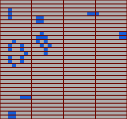
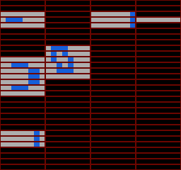
To compute the current generation of Game of Life, the previous generation must remain in-tact. This means that at any point in time, the current and previous generations are both in memory. Bitwise XOR-ing each byte of the current generation with each byte of the previous generation is a quick way to find out which bytes have changed.
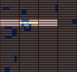
Here’s the second generation above with bytes blacked-out if the bitwise XOR with the corresponding byte in the previous generation is 0 (ie. there was no change in that byte between the two generations).
Since the current video memory address is incremented with every video memory write, there is no need to explicitly set the video memory address between two consecutive strips of 8 tiles. Thus, the draw queue is a sequence of runs of consecutive 8-tile strips.
The draw queue is stored within the first 256 bytes of memory as an optimization, as there are special instructions for accessing this region faster than other regions of memory. The draw queue is made up of variable-length blocks of the form:
- Screen Position: A single byte between 0 and 119 indicating which byte is being updated. To convert this value to a video memory address, multiply it by 8, and add the base nametable address.
- Size: A single byte indicating how many bytes of tile data follow.
- Tile Data: A sequence of Size bytes, where the value of each bit indicates the state of a cell in the current Game of Life generation.
The draw queue is terminated with a negative screen position.
The first few draw queue entries from the example above:
Screen Position: 8
Size: 1
Data:
0x00 (0b00000000)

Screen Position: 10
Size: 1
Data:
0x80 (0b10000000)

Screen Position: 12
Size: 1
Data:
0x1C (0b00011100)

Screen Position: 14
Size: 2
Data:
0x80 (0b10000000)
0x00 (0b00000000)
Note that because updates are specified a byte at a time, some tile updates (many in fact) are redundant (ie. the nametable entry is updated to the value which it already has). Operating on entire bytes at a time is convenient, and allows the state to be represented compactly, but this comes at a cost. I wouldn’t be surprised if there are still large performance gains to be had by updating the display at a finer granularity.
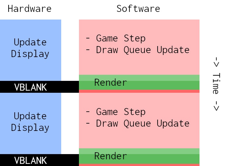
Timing
In the ideal situation, all the application logic would take place outside of VBLANK, while the graphics hardware is busy updating the display. Then the renderer would be invoked. It waits until the start of VBLANK, then begins updating nametable entries, and processes the entire draw queue before the end of VBLANK.
In reality, it often takes several frames to process the draw queue. When the end of VBLANK is getting close, the renderer will spin until the start of the next VBLANK, then continue where it left off.
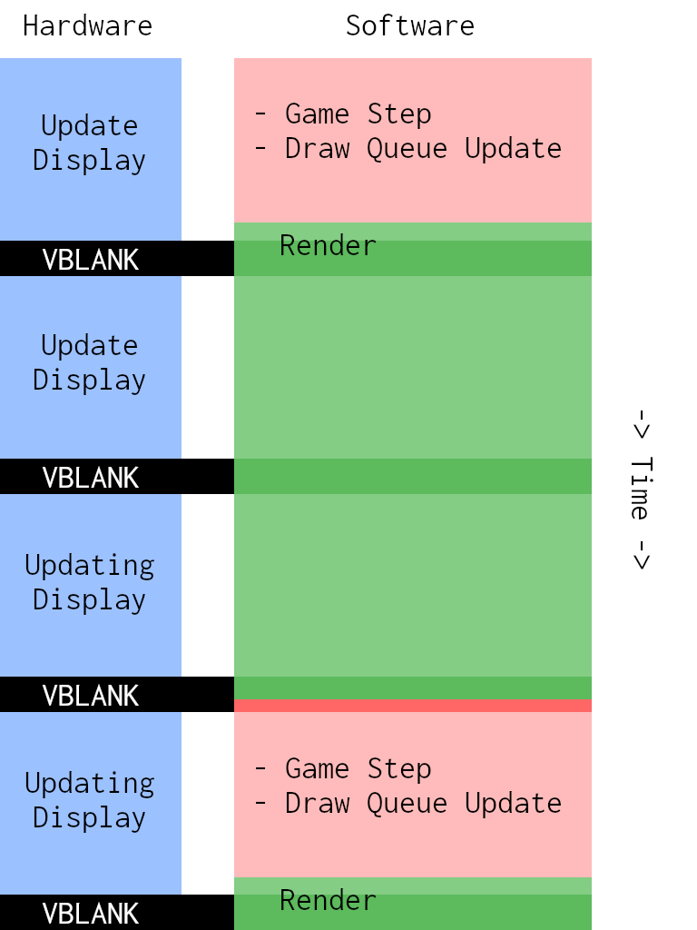
Any changes made to the nametable during a VBLANK interval are visible the next time the display is updated. This is the reason for the vertical wipe artefact visible when the effective framerate is low.
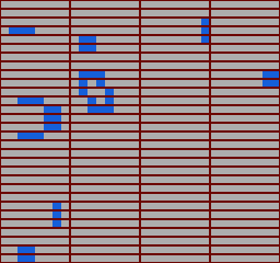
Here’s a visualization of the nametable entries that are written on each frame.

Patterns
The animation above shows the locations in the nametable being written to on each frame. Each nametable entry is a single byte, which is treated as an index into the pattern table. The pattern table is a 4kb region of video memory containing 256 patterns. A pattern is a 16 byte = 128 bit description of an 8 x 8 = 64 pixel tile, where every pair of bits determines the colour of a pixel.
In Game of Life, each cell is either alive or dead, so one approach would be to use 2 patterns. Here pattern 0 represents a dead cell, and 1 represent a live cell. The remaining patterns are unused.
Writing a 0 to a nametable entry would set the corresponding background tile to a dead cell,

and writing a 1 would show a live cell.

In the draw queue, each 8-tile horizontal strip is represented by a single byte, where each bit encodes the state of a cell. To render a byte, iterate over each bit, and send the value of the bit to graphics hardware:
// Note that this is pseudocode!
// I don't compile rust to run on the NES.
// I write assmebly in a rust DSL. See below.

// assume video memory address is already set correctly
let mut byte_to_render = next_byte_from_draw_queue();
for i in 0..8 {

    // take the current bit
    let pattern_index = byte_to_render & 1;

    // assume this increments the current video memory address
    write_to_video_memory(pattern_index);

    // right shift so the next bit can be tested
    byte_to_render = byte_to_render >> 1;
}
This works, but can be improved. The CPU in the NES only has one general purpose register, known as the accumuluator. When bitwise-AND-ing, the current accumulator value is replaced with the result of the AND. In order to right shift and read the next bit, we’d need to backup the original accumulator value, AND it with 1 to get the current bit, write the result to video memory, then restore the original accumulator value from backup before right-shifting. This all has to happen during the precious VBLANK interval.
Observe that pattern_index is 1 precisely when byte_to_render is odd. The pattern table has 256 entries, so every possible
byte is a valid nametable entry. We could remove the need to read the current bit from byte_to_render if we set up the
pattern table such that all odd nametable entries corresponded to a live cell, and all even entries correspond to a dead cell.
The pattern table becomes:
 .
.
Every even entry is dead, and every odd entry is alive.
The code to render a byte can be simplified:
let mut byte_to_render = next_byte_from_draw_queue();
for i in 0..8 {
    // assume this increments the current video memory address
    write_to_video_memory(byte_to_render);

    // right shift so the next bit can be tested
    byte_to_render = byte_to_render >> 1;
}
This translates into simple assembly:
INX        ; increment X index register - the pointer into draw queue
LDA $00,X  ; read next byte from draw queue into accumulator

; unrolled loop

STA $2007  ; store accumulator value at address 0x2007, which writes it to video memory
LSR        ; right shift the accumulator
STA $2007  ; writing 0x2007 increments the current video memory address so repeatedly
LSR        ;   writing 8 times will populate 8 consecutive nametable entries
STA $2007
LSR
STA $2007
LSR
STA $2007
LSR
STA $2007
LSR
STA $2007
LSR
STA $2007
Rust?
About a year ago I made a NES emulator in rust, and wanted to write some small NES programs to test it. I made a small rust library mos6502_assembler for writing assembly programs for the MOS6502 (the processor in the NES). Another small rust library I made as part of my emulator, ines, allows reading and writing NES ROM files in the INES format, which is the standard file format understood by all NES emulators.
// Function to read the state of the controller into address 0x00FF
b.label("controller-to-255");
const CONTROLLER_REG: Addr = Addr(0x4016);

// toggle the controller strobe bit to copy its current value into shift register
b.inst(Lda(Immediate), 1);
b.inst(Sta(Absolute), CONTROLLER_REG); // set controller strobe
b.inst(Sta(ZeroPage), 255); // store a 1 at 255 - used to check when all bits are read
b.inst(Lsr(Accumulator), ()); // clear accumulator
b.inst(Sta(Absolute), CONTROLLER_REG); // clear controller strobe

// shift each of the 8 bits of controller state from the shift register into address 255
b.label("controller-to-255-loop");
b.inst(Lda(Absolute), CONTROLLER_REG); // load single bit into LBS of acculumator
b.inst(Lsr(Accumulator), ()); // shift bit into carry flag
b.inst(Rol(ZeroPage), 255); // shift carry flag into 255, and MSB of 255 into carry flag

// if that set the carry flag, this was the 8th iteration
b.inst(Bcc, LabelRelativeOffset("controller-to-255-loop"));

b.inst(Rts, ()); // return from subroutine
In order for an emulator to decode and emulate instructions, it needs to know the opcode and argument layout of each instruction. The same information is needed by the assembler to generate binary code corresponding to a 6502 program. The definitions of instructions are taken straight from the core of my emulator, another rust library: mos6502_model. It took a little extra work per instruction when making that library to allow it to be used in both my emulator and assembler, but it means that the information for any given instruction is all in the same place.
Pre-Processing
Embedding an assembler in a general-purpose programming language means you get to use the host language as a powerful pre-processor.
In the code example above, the address of the controller register, 0x4016, is assigned to a rust constant CONTROLLER_REG.
The ability to assign values to names is a staple in most assemblers, but when your assembler is embedded in a general purpose language
it’s as simple as a variable/constant assignment!
Another benefit is using host language loops instead of loops in assembly. For loops iterating a small constant number of times, unrolling the loop by repeatedly emitting the code within is easier and faster than writing the loop in assembly.
// zero-out first 8 bytes of memory
b.inst(Lda(Immediate), 0);
for i in 0..8 {
    b.inst(Sta(ZeroPage), i);
}
The 6502 only has 3 registers, so in code with nested loops, it’s common to run out of registers to store loop counters. This isn’t the end of the world - loop counters can be stored in memory, but this is a bit of a pain and incurs a runtime cost, so I frequently use this technique to relieve some of the pressure. Of course this comes at the cost of increased code size. On more modern architectures I’d mention how this hurts locality and will lead to more cache misses, but the 6502 has no cache.
Validation
Another benefit of embedding is the ability to leverage the host type system to validate some properties of the guest program.
Consider the STA instruction, which STores the value of the Accumulator in memory. On the 6502, instructions that take
memory addresses as arguments are parameterized by an “addressing mode”, which determines how the argument is mapped to
an address.
In the example above, there is a line…
const CONTROLLER_REG: Addr = Addr(0x4016);
b.inst(Sta(Absolute), CONTROLLER_REG);
…which has the addressing mode “Absolute”, and an argument of 0x4016. The Absolute addressing mode reads the next 2 bytes after the instruction opcode in memory and treats it as an address (6502 addresses are 16-bit). This line stores the current accumulator value in 0x4016.
The next line is…
b.inst(Sta(ZeroPage), 255);
…which has the addressing mode “Zero Page”, and an argument of 255 (0xFF in hex). The Zero Page addressing mode reads a single byte after the instruction opcode, and treats it as an index into the first 256 bytes of memory (ie. the “zero page” in 6502 parlance). This line stores the current accumulator value at address 0x00FF.
A third addressing mode, “Immediate”, reads a single byte after the instruction opcode and treats it as a literal value rather than an address.
b.inst(Lda(Immediate), 42); // Load the accumulator with the value 42
It’s only meaningful when the instruction would read from memory. Using the Immediate addressing mode with the STA is impossible, as it doesn’t make sense to store the current accumulator value at a literal value.
Rather than writing a check to prevent illegal instructions from being compiled, I encode the valid addressing modes for each instruction in the type system.
If I tried to write this…
b.inst(Sta(Immediate), 42); // Store the accumulator with the value 42
…it would be a type error:
error[E0277]: the trait bound
  `mos6502_model::addressing_mode::Immediate: mos6502_model::instruction::sta::AddressingMode`
  is not satisfied
   --> conway/src/main.rs:609:5
    |
609 |     b.inst(Sta(Immediate), 42); // Store the accumulator with the value 42
    |     ^^^^^^^^^^^^^^^^^^^^^^^^^^^ the trait `mos6502_model::instruction::sta::AddressingMode`
    |                                 is not implemented for
    |                                 `mos6502_model::addressing_mode::Immediate`
    |
    = note: required by `mos6502_model::instruction::sta::Inst`
Game of Life
The state of the 960 cells is stored in a 120 byte array, which is initialized randomly using a simple random number generator (32-bit Xorshift) seeded by the number of frames since start up. Computing the second generation of the automata populates a second 120 byte array with the new cell states. The third generation overwrites the first cell states, the fourth overwrites the second, and so on. At any point, the previous 2 generations of cells are present in a pair of arrays.
Update 8 Cells at a Time
As each byte of state represents the state of 8 cells, it’s convenient to compute the new cell states 8 at a time - that is, one byte of state at a time. For each bit of the current byte, count the living cells adjacent to the cell represented to that bit. Build up all 8 counts at the same time. This way, for each byte, only 9 bytes (the 8 neighbouring bytes, and the current byte itself) need to be read from memory.

The method of incrementing living neighbour count of a cell based on a neighbouring byte depends on which neighbour it is. For example in the byte above the current byte, each bit is neighbour to the corresponding bit in the current byte, as well as the bit one to the left, and the bit one to the right (diagonal adjacency counts as adjacency). In the byte which is down and to the left of the current byte, only the left-most bit need be considered. The cell represented by this bit is only adjacent to the right-most bit of the current byte.

Once all the living neighbours of each of the 8 cells have been counted, the state of the corresponding cells in the next generation is decided based on the living neighbour counts and current cell states.
Precomputed Neighbours
To compute the next state of an 8-cell strip, the 8 neighbouring bytes in the 4x30 byte grid need to be considered.
Computing the indices of the neighbours of a cell with a given index is not a hard problem, but computing the 8 neighbours of each of the 120 bytes is still a non-trivial amount of work for the NES to do each frame, especially when dealing with the fact that bytes along the edges of the grid don’t have neighbours on some of their sides.
The indices of the first few rows of the grid are:
 0 |  1 |  2 |  3
 4 |  5 |  6 |  7
 8 |  9 | 10 | 11
 ...
The rust code that generates the rom precomputes the indices of neighbours of each byte, in the order top, bottom, left, top-left, bottom-left, right, top-right, bottom-right.
X,4,X,X,X,1,X,5 | X,5,0,X,4,2,X,6  | X,6,1,X,5,3,X,7   | X,7,2,X,6,X,X,X
0,4,X,X,X,5,1,9 | 1,9,4,0,8,6,2,10 | 2,10,5,1,9,7,3,11 | 3,11,6,2,10,X,X,X
...
The X’s in the table above indicate neighbours which don’t exist, because the byte
is on the edge of the grid. In the precomputed neighbour table, the value 120 is used
in place of X. There are 120 bytes in the state, with indices ranging from 0 to 119.
After the last byte of state, at offset 120, I store the value 0.
Thus when reading the neighbouring byte of a byte with no such neighbour, a 0 is read instead.
It is as if the visible area of the grid were surrounded by a border of cells which are always dead.
Source Code
All my NES-related rust libraries and executables are in this repo.
Outtake
When I first implemented Game of Life and ran it on a simple configuration of gliders it mostly worked, but exploded when the frame-to-frame difference became zero.

When populating the draw queue, I wasn’t handling the case where there is no frame-to-frame difference. As a result, the renderer was getting stuck in a loop updating video memory. The visual artefacts are caused by updating current video memory address outside of VBLANK.
About half-way through the clip there is a frame where the screen shakes (before it totally crashes). This was caused by the renderer continuing to run slightly passed the end of VBLANK, and as above, updated the current video memory address.
In a previous blog post I explain these glitches in more detail, and show how the original Legend of Zelda used them to great effect to implement scrolling: Zelda Screen Transitions are Undefined Behaviour