Component Pinouts
This page will list pinouts of some electronic components I commonly find myself using, as well as some notes on using them that might not be obvious from reading the datasheets.
78L05 Voltage Regulator in TO-92 package
Datasheet (pdf) for L78L series voltage regulators which includes the 78L05
The 78L05 provides a regulated 5v supply on its output pin if sufficient voltage (at least 7v) is supplied to its input. If a device’s documentation says that the device requires a regulated 5v power supply, this is the kind of thing that it means.
The TO-92 package is commonly used for transistors but other 3-pin components can also be found in this package.
The pinout in the datasheet is from the bottom-up point of view which I found counterintuitive and possibly dangerous for people skimming the manual looking for a pinout without reading the text indicating it’s a bottom-up view.
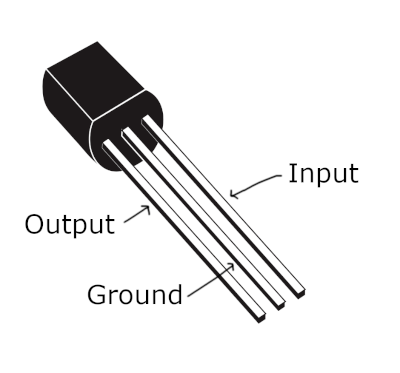
The component has a round side and a flat side. As shown in the image above, with the flat side facing you, with the pins pointing downwards:
- The left pin is the output and will provide 5V if sufficient voltage (at least 7v) is supplied to the input.
- The middle pin is ground.
- The right pin is the input.
The figure of 7v as the minimum input voltage is based on this image from the
manual:
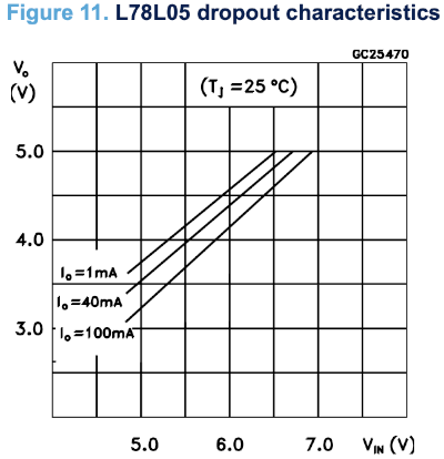
So the actual minimum input voltage depends on how much current is being drawn from the output, but if it’s up to 100mA then 7v will be fine.
LM358 and TL072 Dual Op Amps
Datasheet (pdf) for LM385 Dual Op Amp (also contains information on related components)
Datasheet (pdf) for TL072 Dual Op Amp (also contains information on related components)
Both components include a pair of op amps on a single chip and they have identical pinouts. This is the pinout viewed from top-down:
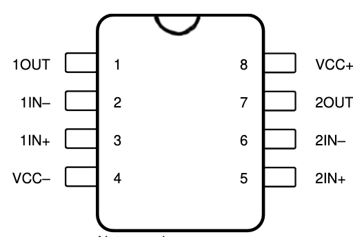
This table lists the pins corresponding to their arrangement in the diagram above. The semi-circular indentation on the top of the IC is facing upwards.
| Left Side | Right Side |
|---|---|
| 1OUT | VCC+ |
| 1IN- | 2OUT |
| 1IN+ | 2IN- |
| VCC- | 2IN+ |
My mnemonic for this pinout is that the bottom left is usually ground and the top right is usually positive voltage for ICs, and if you don’t have a negative supply voltage you’ll probably connect the VCC- pin to ground. Then, a common op amp feedback configuration is a voltage forwarder (aka. a buffer amplifier) and in this configuration the IN- pin and the OUT pin are connected together. I like to pretend that the designer wanted to make it easy to setup a voltage forwarder by putting the OUT and IN- pins next to each other for both op amps on the chip.